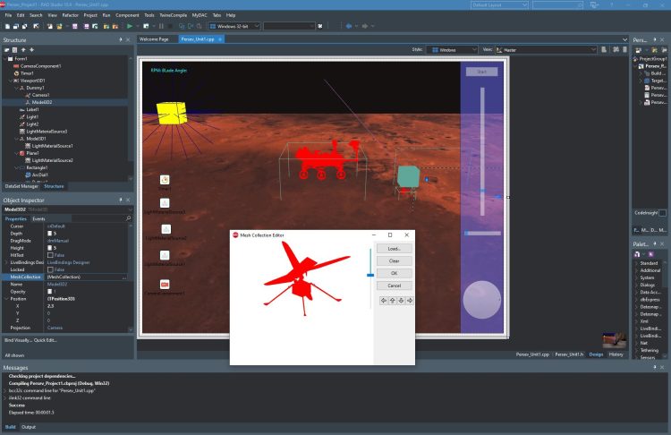
Do you want to develop your own Mars Simulation with the latest Mars Perseverance Rover 3D Model or Mars Ingenuity Helicopter 3D Model? C++ Builder is very easy to develop this kind of simple simulations. You just need a 3D object model and some colors, lights, a camera, maybe some textures. This same method and results can be obtained in Delphi too.
We highly recommend you to read this previous post Learn to Develop a Perseverance Mars Simulation 3D in C++ Builder
Do you want to fly Mars Ingenuity Helicopter with Mars Physics? Let’s see how it is easy to do a simulation.
Simplified Ingenuity Fly Theory
For any helicopter, the Lift force can be written in this formula,

We don’t have too many details about the physical parameters of Ingenuity and this formula requires shape details to integrate.
We only know Ingenuity flies at 2400 rpm = 2400/60 = 40 1/s and angular velocity w=2xPIxf = 2xPIx40 . To calculate lift force in speed changes, we can use the formula above, all other parameters can be assumed as a constant K. Thus, Lift force can be simplified for this simulation as below,
|
1 2 3 |
L = K x w^2 |
And we know that Ingenuity has 1.8kg mass and gravity at Mars is 3.711 m/s2 that means Weight of Ingenuity is equal to,
|
1 2 3 4 5 6 |
W = m x g ( or f = m x a) W = 1.8 x 3.711 W = 6.68 kgm/s2 W = 6.68 Nt |

Lift force should be higher than this Weight at the maximum RPM, So let’s assume Maximum Lift Force Lmax is %20 higher than this force (or you can assume 8 Nt)
|
1 2 3 4 5 |
Lmax = W x 1.20 Lmax = 6.68 x 3.711 Lmax = 8.016 Nt |
Now, we can find K without knowing the geometry as below,
|
1 2 3 4 |
L = K x w^2 8 = K x (2xPIx40)^2 K = 0.0001267 |
Now if we put this K to lift formula
|
1 2 3 |
L = 0.0001267 x w^2 |
We can simulate lifting up by the F net force in y+ direction as below,
|
1 2 3 |
F = L - W |
We can find acceleration, velocity and Y in y direction;
|
1 2 3 4 5 |
a = F / m; V = V + a*t; X = X + V*t; |
Now we can use these simplified formulas to simulate Ingenuity flight
Developing 3D C++ Application

- Create a new C++ Builder Multi-Device FMX Project, Save all Unit and Project files to a folder (i.e. IngenuitySim)
- We will use Viewport3D to display our 3D environment (scene). Drag a TViewport3D onto your Form. Set UseDesign Camera property to false, because we will use our camera to view objects in this scene.
- Add TCamera from the 3D Scene group in Tools Palette, Set its Position->Z to -10
- We will use Model3D to display our 3D object. Drag TModel3D
- We need some lights, Drag TLight from the Tools Palette to the ViewPort3D. Set its LightType to Point and its Position->Y to -10 in the Object Inspector window.
- and we need MaterialSource to display it in colors, Add a LightMatrialSource from the Tools Palette
- Now let’s download Ingenuity Helicopter 3D Model in *.GLB format from Official Nasa’s Perseverance Rover Lands on Mars Web Page. Here you can download both Mars Perseverance Rover and Mars Ingenuity Helicopter, 3D models.
- We can only load *.DAE, *.ASE or *.OBJ based 3D object format into our Model3D. So, we should convert this GLB to DAE. Go to free online GLB 3D object file format to DAE 3D object file format converter web page here. Drag the GLB model here to convert DAE. Submit and wait to be converted. This may take few minutes, then save it to your project folder.
- Now back to RADS, designer. Select Model3D1 and double click to its MeshCollection to load our 3D Model Object.
- Press the Load.. button to Load our converted Rover object in *.DAE format. This may take few minutes, wait till you see 3D Rover in Mesh Collection Editor.
- Press the OK button to apply this to our Model3D1. This may take few minutes, wait till you see a 3D rover in your Viewport.
- Set Depth, Height, Width of the Model3D to 5, so you can see better. You can set its Position and RotationAngles too.
- Add right Panel as above with 2 Sliders and one ArcDial,
- Add Dummy1 object and drag Model3D and Camera into this, we will move and use Dummy1 as Ingenuity Model so both Camera and Model3D will move together.
- Finally we need a Label that has 800px width to give information in one line;
Let’s define constants and variables;
|
1 2 3 4 5 6 7 8 9 10 11 12 13 14 15 16 17 18 19 20 21 22 23 24 |
int part=0, number_of_parts; float rpm = 0; // rotor revolutions per minute float rot = 0; // rotor revolutions per interval time float ang = 0; // blade angle (assumption) float tet = 0; // directional angle at X-Z plane float ay = 0, // acceleration Vy = 0, // velocity X = 0, Z = 0, Y = 0, // position F = 0; // Net Vertical Force = L-W const float m = 1.8; // Total mass of Ingenuity const float g = 3.711; // Gravity on Mars = 3,711 m/sn² const float W = m*g; // Total weight on Mars float L; // lift force const float Lmax = W*1.20; // Let's assume lifting force 20% higher weight or assume 8 Nt const float wmax = 2400/60*2*M_PI ; // maximum angular velocity; float K = Lmax/wmax/wmax; // assumed lifting constant for the simulation String str; |
We can easily rotate blades (Part 26 and 27) as below with a OnTimer event;
|
1 2 3 4 5 6 7 |
void __fastcall TForm1::Timer1Timer(TObject *Sender) { Model3D2->MeshCollection[27]->RotationAngle->Y+=rot; Model3D2->MeshCollection[26]->RotationAngle->Y-=rot; } |
We can also update the position of Ingenuity as below,
|
1 2 3 4 5 6 7 8 9 10 11 12 13 |
void __fastcall TForm1::Timer1Timer(TObject *Sender) { Model3D2->MeshCollection[27]->RotationAngle->Y+=rot; Model3D2->MeshCollection[26]->RotationAngle->Y-=rot; Viewport3D1->BeginUpdate(); Dummy1->Position->Y = -1*Y; Dummy1->Position->X = X; Dummy1->Position->Z = Z; Viewport3D1->EndUpdate(); } |
Let’s add our calculations into this OnTimer event,
|
1 2 3 4 5 6 7 8 9 10 11 12 13 14 15 16 17 18 19 20 21 22 23 24 25 26 27 28 29 30 31 32 33 34 35 36 37 |
void __fastcall TForm1::Timer1Timer(TObject *Sender) { rpm = 2400-TrackBar1->Value; rot = rpm/60*(Timer1->Interval/1000.0)*360; ang = 0.1*TrackBar2->Value/360.0; tet = M_PI*ArcDial1->Value/180.0; L = K*pow( rpm*2*M_PI/60.0, 2); F = L - W; ay = F/m; Vy += ay*(Timer1->Interval/1000.0); Y = Max( 0.0, Y+Vy*(Timer1->Interval/1000.0) ); X += ang*Cos(tet); Z += ang*Sin(tet); if(Y<=0.0001) Vy = 0; Viewport3D1->BeginUpdate(); Dummy1->Position->Y = -1*Y; Dummy1->Position->X = X; Dummy1->Position->Z = Z; Model3D2->RotationAngle->X = 180 + 2*Cos(tet); Model3D2->RotationAngle->Z = 2*Sin(tet); Viewport3D1->EndUpdate(); str.printf(L"Rotation:%6f rpm Blade Angle:%6.1f Lift Force:%6.1f Nt Net Force:%6.1f Nt ay:%8.2f m/s2 Vy:%8.2f m/s Y:%6.1f m", rpm, ang, L, F, ay, Vy, Y); Label1->Text=str; Label1->Repaint(); Model3D2->MeshCollection[27]->RotationAngle->Y+=rot; Model3D2->MeshCollection[26]->RotationAngle->Y-=rot; } |
We should initialize some parameter at the beginning. Here is the full example to fly Ingenuity in C++ Builder,
|
1 2 3 4 5 6 7 8 9 10 11 12 13 14 15 16 17 18 19 20 21 22 23 24 25 26 27 28 29 30 31 32 33 34 35 36 37 38 39 40 41 42 43 44 45 46 47 48 49 50 51 52 53 54 55 56 57 58 59 60 61 62 63 64 65 66 67 68 69 70 71 72 73 74 75 76 77 78 79 80 81 82 83 84 85 86 87 88 89 90 91 92 93 94 95 96 97 98 99 100 101 102 103 104 105 106 107 108 109 110 111 112 113 114 115 116 117 118 119 120 |
//--------------------------------------------------------------------------- #include <fmx.h> #pragma hdrstop #include "Persev_Unit1.h" //--------------------------------------------------------------------------- #pragma package(smart_init) #pragma resource "*.fmx" TForm1 *Form1; int part=0, number_of_parts; float rpm = 0; // rotor revolutions per minute float rot = 0; // rotor revolutions per interval time float ang = 0; // blade angle (asumption) float tet = 0; // directional angle at X-Z plane float ay = 0, // acceleration Vy = 0, // velocity X = 0, Z = 0, Y = 0, // position F = 0; // Net Vertical Force = L-W const float m = 1.8; // Total mass of Ingenuity const float g = 3.711; // Gravity on Mars = 3,711 m/sn² const float W = m*g; // Total weight on Mars float L; // lift force const float Lmax = W*1.20; // Let's assume lifting force 20% higher weight or assume 8 Nt const float wmax = 2400/60*2*M_PI ; // maximum angular velocity; float K = Lmax/wmax/wmax; // assumed lifting constant for the simulation String str; //--------------------------------------------------------------------------- __fastcall TForm1::TForm1(TComponent* Owner) : TForm(Owner) { number_of_parts = Form1->Model3D1->MeshCollection.Length; // SETTING MATERIALS OF PERSEVERANCE Form1->Model3D1->BeginUpdate(); for(int i=0; i<number_of_parts; i++) { Form1->Model3D1->MeshCollection[i]->MaterialSource=LightMaterialSource1; } Form1->Model3D1->EndUpdate(); Form1->Model3D1->Repaint(); // SETTING MATERIALS OF INGENUITY Form1->Model3D2->BeginUpdate(); number_of_parts = Form1->Model3D2->MeshCollection.Length; for(int i=0; i<number_of_parts; i++) { Form1->Model3D2->MeshCollection[i]->MaterialSource=LightMaterialSource1; } Form1->Model3D2->EndUpdate(); Form1->Model3D2->Repaint(); number_of_parts = Form1->Model3D2->MeshCollection.Length; // SETTING MATERIALS OF BLADES Form1->Model3D2->MeshCollection[27]->MaterialSource = LightMaterialSource3; Form1->Model3D2->MeshCollection[26]->MaterialSource = LightMaterialSource3; } //--------------------------------------------------------------------------- void __fastcall TForm1::Button1Click(TObject *Sender) { if(Timer1->Enabled) { Timer1->Enabled=false; TrackBar1->Value=2000; Button1->Text="START"; } else { Timer1->Enabled=true; Button1->Text="STOP"; } } //--------------------------------------------------------------------------- void __fastcall TForm1::Timer1Timer(TObject *Sender) { rpm = 2400-TrackBar1->Value; rot = rpm/60*(Timer1->Interval/1000.0)*360; ang = 0.1*TrackBar2->Value/360.0; tet = M_PI*ArcDial1->Value/180.0; L = K*pow(rpm*2*M_PI/60.0, 2); F = L - W; ay = F/m; Vy += ay*(Timer1->Interval/1000.0); Y = Max( 0.0, Y+Vy*(Timer1->Interval/1000.0) ); X += ang*Cos(tet); Z += ang*Sin(tet); if(Y<=0.0001) Vy = 0; Viewport3D1->BeginUpdate(); Dummy1->Position->Y = -1*Y; Dummy1->Position->X = X; Dummy1->Position->Z = Z; Model3D2->RotationAngle->X = 180 + 2*Cos(tet); Model3D2->RotationAngle->Z = 2*Sin(tet); Viewport3D1->EndUpdate(); str.printf(L"Rotation:%6f rpm Blade Angle:%6.1f Lift Force:%6.1f Nt Net Force:%6.1f Nt ay:%8.2f m/s2 Vy:%8.2f m/s Y:%6.1f m", rpm, ang, L, F, ay, Vy, Y); Label1->Text=str; Label1->Repaint(); Model3D2->MeshCollection[27]->RotationAngle->Y+=rot; Model3D2->MeshCollection[26]->RotationAngle->Y-=rot; } //--------------------------------------------------------------------------- |
When you run you will see blades are rotating and flies when you increate it’s rpm by the vertical slider. Net force should be positive to move up and negative to move down.


Final Words,
This is a very simple example to show how to simulate a helicopter in 3D. In a more real simulation, we need to use matrix forms with rotation matrix to define effect of F force on X Y Z directions, atmospheric density can be considered here and it may vary with temperature changes, … etc . We know you can do better.
Design. Code. Compile. Deploy.
Start Free Trial
Free C++Builder Community Edition

